CANtrace Help
A powerful CAN bus analyser software and diagnostic tool
This tab is used for sending CAN messages to configured channels. Messages can be configured manually or added from an associated database file. Message signal values are easily modified using the signal value editor view.
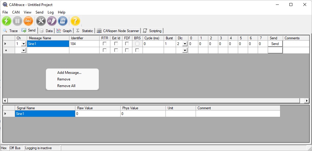
Figure 10.3 Send tab user interface
When right-clicking on the window a menu appears with the following options:
| Add Message… | Adds a new message from the associated databases |
| Remove | Removes chosen message |
| Remove All | Removes all messages in send tab |
The Send tab is divided into thirteen sections. Description for each section is displayed in table 10.2.
Table 10.2 Send message columns explanation
| Column name | Column Description |
| Ch | The channel the CAN message is sent on |
| Message name | Name of message from associated database |
| Identifier | The CAN Message ID |
| RTR | Is the CAN message a RTR message |
| Ext Id | Is the CAN message ID extended |
| FDF | Is the message a CAN FD message |
| BRS | Is bit rate switching used for this message. |
| DLC | Data Length of message |
| Cycle (ms) | Time between frames in milliseconds. When cycle time is 0 ms, only a single message or burst will be sent. Cycle accepts values between 0 and 5000000 |
| Burst | How many messages that are being sent after each other without any delay. Burst accepts value between 1 and 100 |
| Data (0-7) | Data to be sent. Max length of a message is 8 byte. The maximum value is 255 in decimal and FF in hexadecimal |
| Send-Button | When Send button is pressed the corresponding row of data is sent as a message |
| Comment | Description or note about the CAN message |
This section explains how CAN messages are sent using the Send tab. CAN messages can also be sent using The Log Playback functionality or using the Scripting Tab.
Manually configuring a CAN message:
Configuring a CAN message from an associated database:
CAN messages can also be sent by configuring a log file to be played back to a channel. This is explained in more detail in the Play Log File Settings chapter.
Note: Ensure that the configured devices in the CANtrace project are plugged in and activated. The send buttons are disabled in the bus off state, when going on bus the send buttons for messages with a correclty configured channel become active. Messages are sent by clicking the Send button for each message you wish to transmit.
The Scripting tab can also be used to send CAN messages. With the Scripting tab functionality CAN messages with dynamic data can be created. This is explained in more detail in the Scripting Tab chapter.
To remove a message, click on the beginning of the row, so that the whole row is highlighted. Then right-click and select Remove to remove that message.
To remove all the messages on Send tab, right-click and select Remove All.
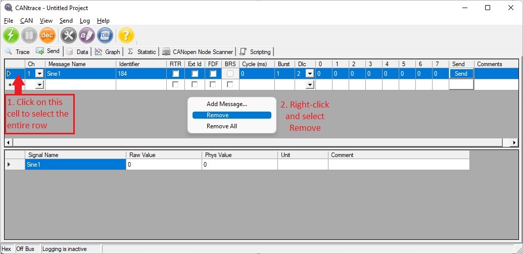
Figure 10.5.1 Remove one message
CANtrace supports simple signal multiplexing, where one multiplexor per message is used.
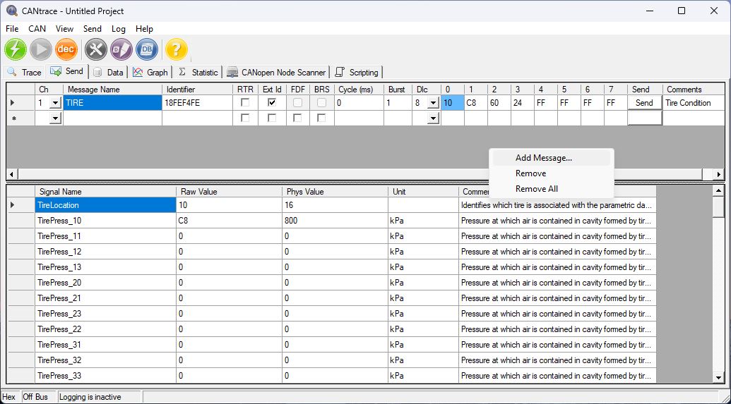
Figure 10.5.2 Send Message
Note: The light blue color (representing Data byte 0) indicates that the corresponding CAN message contains a Multiplexor Signal.
When you add the Multiplexor Signal from the Database, it will display the corresponding CAN message in the Data byte list.
The Data byte will update when you change the Raw Value or Phys Value of the multiplexor signal, provided the value matches one of the multiplex values.
When you change the Data byte in the list, if the value of the multiplexor signal matches one of the multiplex values, the multiplex Raw Value and Phys Value will be updated automaticaly.

TK Engineering Oy
Hovioikeudenpuistikko 13 as 3
65100 Vaasa, Finland
Kauppakatu 3 B
33200 Tampere, Finland
info@tke.fi
Phone: +358 6 357 6300
