CANtrace Help
A powerful CAN bus analyser software and diagnostic tool
When analyzing a CANopen network, the CANopen Node Scanner tab can be used to automatically detect active CANopen nodes on the network based on the received boot-up messages. The window provides the user NMT functionality to easily control the found nodes.
By right-clicking on the window and choosing Reset the user can clear the window of found nodes. Found nodes will be displayed again when new boot up messages are received.
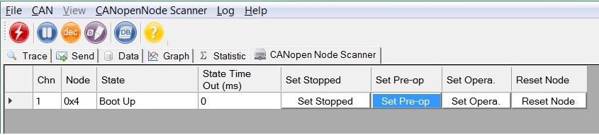
Figure 10.13 CANopen NodeScanner view
Table 10.9 CANopen Node scanner Columns explanation
| Column Name | Column Description |
| Chn | Application channel |
| Node | Displays the CAN ID of the CANopen node in hexadecimal |
| State | Displays the NMT state of the corresponding node |
| State Time Out | Time between heartbeats, before Node Scanner treats current node as inactive |
| Set Stopped | Set the node to Stopped mode. (NMT 0x2) |
| Set Pre-op | Set the node to Pre-operational mode. (NMT 0x80) |
| Set Opera. | Set the node to Operational mode. (NMT 0x1) |
| Reset Node | Reset the node. (NMT 0x81) |
When State Time Out (ms) is set to 0, then timeout is disabled. Found nodes are not treated as inactive even if they don’t produce a heartbeat.
The State column displays the state of the node.
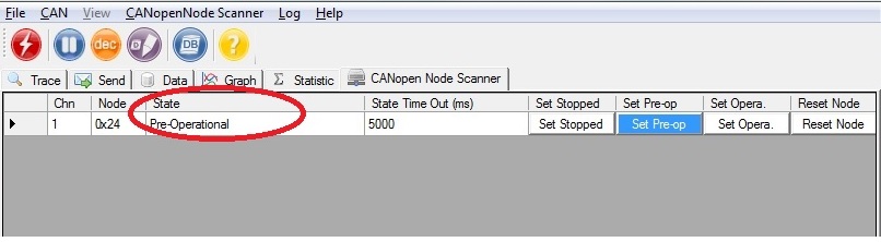
Figure 10.14 Node State display
By pressing the Set buttons, you can set the current node to the desired NMT state.
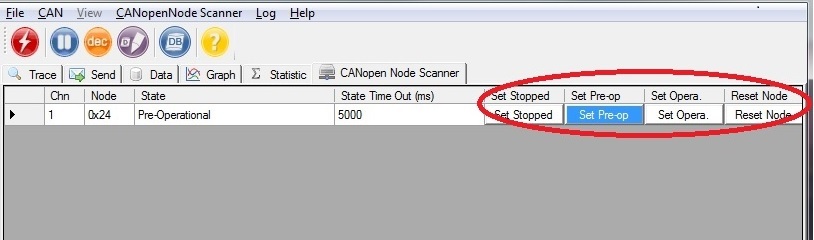
Figure 10.15 Controlling nodes state

TK Engineering Oy
Hovioikeudenpuistikko 13 as 3
65100 Vaasa, Finland
Kauppakatu 3 B
33200 Tampere, Finland
info@tke.fi
Phone: +358 6 357 6300
