• Shopping Cart Shopping Cart
    0Shopping Cart
TK Engineering Oy
  • Businesses
    • Defence
    • Energy
    • Marine
    • Off-Highway Vehicles
  • Services
    • Control system design
    • Testing & Troubleshooting
    • Research / Pre-Study
    • Product development
    • Training
  • IoE by TKE
    • Sensing Network
    • IoEX Gateway
    • Human as a Sensor
    • Analytics
  • Products
    • CANtrace
    • CAN bus
    • Automation
    • Telematics
    • Manufactures
  • Articles
    • Case Studies
    • News
    • Research and publications
    • New products
  • Company
    • Cyber Security
    • Partners
    • Distributors
    • Careers
  • Contact us
  • Shop
  • Menu Menu

CANtrace Help

A powerful CAN bus analyser software and diagnostic tool

  • CANtrace features
  • Knowledge base
  • Get CANtrace

7. Peak Settings

7.1 Peak CAN Settings

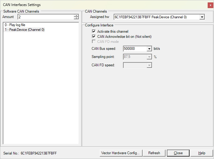
CAN Settings is used for setting up your CAN interface correctly according to the CAN bus. For Peak interface, the license is bound to the computer’s serial number.

The figure below shows a Peak interface that has been assigned to software channel 1. The serial number used to generate the license for the Peak interface can be found in the lower-left corner of the dialogue box.

Figure 7.1 Peak Settings

Software channel
You may define which Software Channel you assign the CAN interface to. It is good to know the software channel when you are for example sending a CAN message.

Activate this channel
If you have installed Peak drivers you may select Activate this channel in order to start using the Peak drivers.

CAN Acknowledge bit on (Not silent)
Here you can configure the CAN interface to work in silent mode (won’t transmit anything, won’t set the ACK bit of the received messages) if the CAN interface supports silent mode.

CAN-Bus Speed
Here you can select the baudrate of the CAN bus. The supported baudrates for Peak CAN interfaces are: 1 Mbit/s, 800 kbit/s, 500 kbit/s, 250 kbit/s, 125 kbit/s 100 kbit/s, 83,3 kbit/s, 50 kbit/s, 20 kbit/s, 10 kbit/s and 5 kbit/s

Sampling point
It’s not possible to set the sampling point for Peak devices.

Refresh
You can click Refresh to rescan the CAN interfaces that are connected to the PC.

Close
If you have finished configuration you can click Close to save and exit the CAN setting form.

Help
Help will open this CANtrace document in case you need some guidance while setting up CAN interfaces.

7.2 Limitations of Peak Interface

There are a few limitations to the Peak Interface when used in CANtrace.

  • Up to two Peak USB interfaces can be in use simultaneously.
  • There is no CAN error frame reporting.
  • The sampling point cannot be configured.
  • The timestamp of transmitted message is not supported by the Peak Driver, thus PC clock is used to generate the timestamps. If the PC supports a high-resolution performance counter, the timestamp has an accurary of about 1ms.

Content

  • CANtrace 4.1
  • Imporant
  • Getting Started
  • Database
  • CastorUSB Settings
  • Vector Settings
  • Kvaser Settings
  • Peak Settings
  • Softing Settings
  • Play Log File Settings
  • Tab Views – Trace Tab
  • Tab Views – Send Tab
  • Tab Views – Data Tab
  • Tab Views – Graph Tab
  • Tab Views – Statistic Tab
  • Tab Views – CANopen NodeScanner Tab
  • Tab Views – Scripting Tab
  • Log Settings
  • Database Log Settings
  • Log File Description
  • License
  • CANopen
  • J1939
  • CAN FD
  • Logging with a Memorator
  • Acknowledgements

TK Engineering Oy

Hovioikeudenpuistikko 13 as 3
65100 Vaasa, Finland

Kauppakatu 3 B
33200 Tampere, Finland

info@tke.fi
Phone: +358 6 357 6300

Highest creditworthiness
© Copyright - TK Engineering Oy Privacy and cookies policy
Scroll to top