How to Quickly Install the WCS-10 Without Errors
Installing the WCS-10 quickly and correctly is essential for maintaining reliable CAN network communications, particularly in marine environments. The process requires careful preparation and attention to detail, but can be completed efficiently by following a structured approach. This guide walks you through the complete installation process from preparation to verification, helping you avoid common pitfalls and ensure your WCS-10 functions optimally from the start.
Understanding the WCS-10 and its importance in CAN networks
The WCS-10 is a specialized CAN bus bridge device designed to facilitate reliable communication between different CAN networks in marine and industrial applications. It functions as a critical connection point that intelligently manages data flow between separate CAN segments.
This marine-grade device serves as both a physical and logical bridge, allowing for seamless integration of various CAN systems while preventing network overloads. The WCS-10 features rugged construction, galvanic isolation, and specialized filtering capabilities that protect sensitive equipment from electrical interference and communication conflicts.
In marine applications, the WCS-10 plays a vital role in connecting engine control systems, navigation equipment, and vessel monitoring networks. Proper installation ensures critical safety systems remain operational, prevents communication bottlenecks, and maintains data integrity across the vessel’s entire control infrastructure.
What are the prerequisites for WCS-10 installation?
Before installing the WCS-10, ensure you have all necessary hardware, software, and technical knowledge. This preparation will significantly reduce installation time and prevent potential errors.
Required hardware includes:
- The WCS-10 device itself
- Appropriate mounting hardware (screws, brackets)
- CAN cables with proper termination (typically 120Ω)
- Power supply connections (24V DC recommended)
- Crimping tools and cable glands for marine-grade installations
- Multimeter for testing connections
Technical prerequisites include:
- Access to your vessel’s or system’s CAN network documentation
- Understanding of the CAN message filtering requirements
- Knowledge of proper grounding techniques for marine environments
- Identification of appropriate installation location (protected from moisture, excessive heat, and vibration)
- Verification of compatibility with existing CAN networks (baud rates, protocols)
Ensure you’ve also allocated sufficient time for installation and testing, as rushing the process often leads to errors that can be time-consuming to troubleshoot later.
How do you install the WCS-10 in 5 simple steps?
Installing the WCS-10 can be completed efficiently by following these five key steps, allowing for quick implementation while ensuring reliable operation.
Step 1: Mount the device
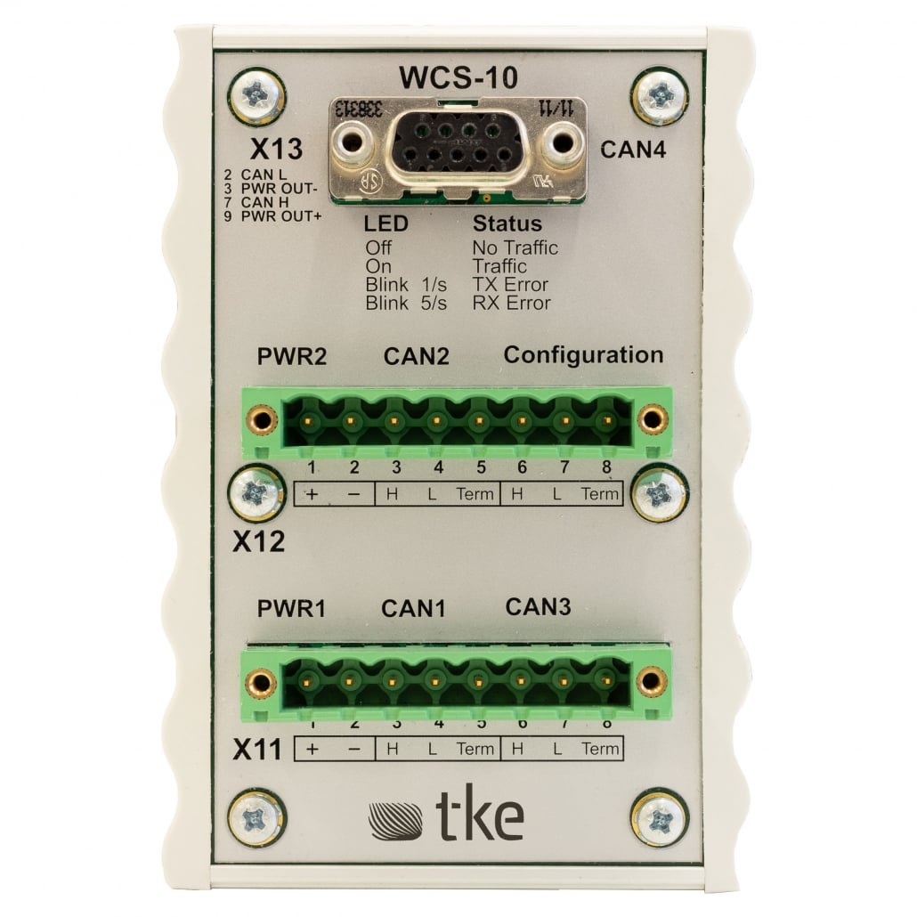
Connect the device to a stable 24V DC power source with appropriate fusing. Ensure proper polarity by connecting the positive wire to the ‘+’ terminal and negative to the ‘-‘ terminal. Verify connections with a multimeter before powering on.
Step 3: Connect CAN networks
Set the appropriate DIP switches according to your filtering requirements. The standard configuration allows all messages to pass between networks, but specific filtering can be applied based on CAN IDs. Consult the product manual for detailed configuration options relevant to your application.
Step 5: Perform initial testing
Power up the device and verify the status LEDs indicate proper operation. The power LED should be constantly illuminated, while the CAN activity LEDs should flash when messages are being transmitted. Use diagnostic software to confirm messages are passing correctly between networks.
What are the most common WCS-10 installation errors and how to avoid them?
Several common installation errors can prevent the WCS-10 from functioning correctly. Identifying these pitfalls beforehand will save significant troubleshooting time.
The most frequent error is incorrect termination of CAN networks. Each CAN segment should have exactly two 120Ω terminators—one at each physical end of the network. Adding the WCS-10 without properly addressing termination can cause signal reflections and communication failures. Ensure you understand the existing network topology and adjust termination accordingly when installing the bridge.
Other common installation mistakes include:
- Improper grounding, leading to ground loops and electrical noise
- Exceeding maximum cable length specifications for CAN segments
- Incorrect baud rate settings between connected networks
- Inadequate power supply or voltage fluctuations
- Exposure to moisture or excessive vibration
- Reversed CAN_H and CAN_L connections
To avoid these issues, carefully follow the installation guide, double-check all connections before powering on, and verify network communications incrementally rather than assuming everything will work immediately after installation.
How can you verify the WCS-10 is working correctly after installation?
After installation, thorough verification ensures the WCS-10 is functioning as expected. Begin by checking all status indicators on the device—the power LED should be solid, while communication LEDs should flash when messages are transmitted.
For comprehensive verification, use a CAN bus analyzer to monitor traffic flow between networks. The analyzer should show messages passing between the connected CAN segments according to your configured filtering rules. Verify that critical messages are being transmitted correctly and that no error frames are being generated.
Practical tests include:
- Triggering actions on one network and confirming the expected response on the other
- Checking system functionality under various operational conditions
- Monitoring message latency to ensure it remains within acceptable parameters
- Testing resilience by simulating high traffic conditions
Document all verification results for future reference, including baseline message counts and response times. This documentation will prove invaluable for troubleshooting any issues that might arise later in the system’s lifecycle.
Key takeaways for successful WCS-10 implementation
Successful implementation of the WCS-10 depends on thorough preparation, careful installation, and comprehensive testing. The most critical factors for error-free installation include proper network termination, correct power supply configuration, and appropriate message filtering setup.
For long-term reliability, implement regular maintenance checks, including physical inspection of connections, verification of termination resistance, and monitoring of message traffic patterns. These preventive measures will help identify potential issues before they cause system failures.
Remember that the WCS-10 is a CAN switch designed for marine environments, so protect it accordingly from moisture, vibration, and temperature extremes. Keeping comprehensive documentation of your specific installation configuration will facilitate future troubleshooting and system expansions.
Should you encounter any challenges during installation or operation, our technical support team is available to provide expert guidance tailored to your specific application requirements.
Explore our other CAN bus products as well!
Interested in real-world automation solutions?
Browse our case studies to discover how we support safe and efficient operations through smart control and networking systems.

