Compensated inclinometers for boom angle measurements
Compensated inclinometers are commonly used for boom angle measurements, when it shall be possible to add sensing into existing systems and when there are not too high accuracy demands. Dynamic conditions lead into corrupted angle values with the traditional, uncompensated inclinometers. Typical target systems are various excavators and cranes.

Shocks and vibration
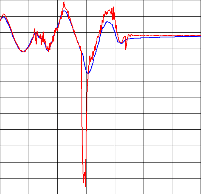
Due to the measurement principle based on acceleration measurement, compensated inclinometers are sensitive to vibrations, shocks and centrifugal acceleration. In the systems, where measurements shall work continuously, uncompensated ones cause significant problems under above mentioned dynamic conditions. Figure 1 illustrates condition, where a boom is driven up and down and finally end of the boom collides to earth. Red curve shows lift boom angle value without compensation and blue curve the compensated value. It is clearly visible in the uncompensated angle value, that moving tilt boom simultaneously with light boom introduces vibration causing jitter to the lift angle.

Figure 1. Normal (red) and Compensated (blue) angle values during shock
Centrifugal acceleration
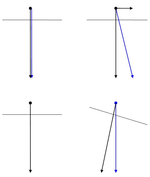
Another, significantly more difficult problem was introduced by rotation of excavator upper frame. Again, due to the acceleration based measurement technology, centrifugal acceleration introduced additional force component in the direction equal to X-component of the angle measurement. Effect of such acceleration is depicted in Figure 2, where steady state is shown on left and dynamic case on right. Top row shows the position of the real mechanics and bottom row, how the uncompensated inclinometer sees the position. Additional acceleration component is marked as X’ and gravitation as G. The erroneus corrupted gravitation R is combination of gravity and additional acceleration caused by rotation of the upper frame. Main paradigm of the angle computing is, that gravity always points downwards. The faster the upper frame is rotated and the more far from rotation centre point the inclinometer is installed, the more significant angle error results.

Figure 2: Illustration of problem caused by centrifugal acceleration (right) compared with the steady state measurement (left)
Some control features, such as monitoring of machine stabilization and prevention of moving parts colliding to other parts of the machine, are depending on the angle measurements. Strong deviations caused by the dynamic use cases lead into serious misbehavior and unnecessary alarms and interrupts to the machine operation.
Development
Customer described the problem to TKE engineers and after only three months diving into the details, the first rapid prototype was under testing in the customers machine. The first rapid prototype supported fully functional shock and vibration compensations, based on which the customer was able to make ”go”-decision for further development. Next milestone was achieved after six months, when first industrial grade hardware was available with centrifugal acceleration compensation developed and implemented. Due to the strong development of sensors semiconductors, it made sense to spend three months for upgrading the sensor in order to improve the overall accuracy. After two months final testing and fine tuning of the compensations, the new CiA-410 compliant inclinometer with full compensations is ready for series production.
Development was performed in co-operation between TKE’s Italian partner company, 3B6. While 3B6 was responsible of the hardware platform design, component logistics and production, TKE took care of the compensation functionality and full CANopen compliance. Sensor was evaluated and selected and calibration was developed in co-operation.


