SI-Unit and scaling management in CANopen
Various kind of inconsistencies have been typical problems in design of distributed control systems. The first solved issue was an automated generation of signal and parameter abstraction from CANopen project avoiding the inconsistent names between application software and communication. The use of meta information of signals and local parameters, such as name, minimum, maximum and default values has already been implemented to avoid the most common inconsistencies.
Producers NMT state is used for monitoring the status of signal producer devices and connections between the devices. Name, network and node identifiers, object index and sub-index are included into meta information of remote parameters to avoid inconsistent parameter accesses. A method for management of CANopen emergency error codes has been introduced to fill the main missing feature of CANopen.
One of the most significant remaining source of inconsistencies in system designs is, how to apply the SI-Units and scaling used by the sensors, actuators and I/O devices to the application programs. Main challenge during the design is that both SI-SI-Unit and scaling may need to be adjusted during the development and it shall be guaranteed that same values will be used by both producer and consumer devices.
CANopen provides an excellent basis for systematic management of the SI-Unit and scaling information by defining representation of SI-Units with prefixes. Some device profiles already support definition of the signal physical units via object dictionary or fixed unit with adjustable scaling. Support of more detailed scaling than just a prefix varies between the device profiles and implementation, because optional objects may also have an effect on SI-Unit and scaling details
Though there is not dedicated meta information for SI-Unit and scaling of object dictionary objects, such information can be synthesized from various parameter object values.
The approach cannot cover all signals and parameters, but provides an excellent workaround while better support is included into corresponding CANopen standards.
The most commonly used device profiles are reviewed and basics of CANopen projects are presented first. Then, an example implementation using combined pressure and temperature transmitter is described in more detailed level. After description of the implementation, discussion of the results and notices are presented. The conclusions are set as a last topic.
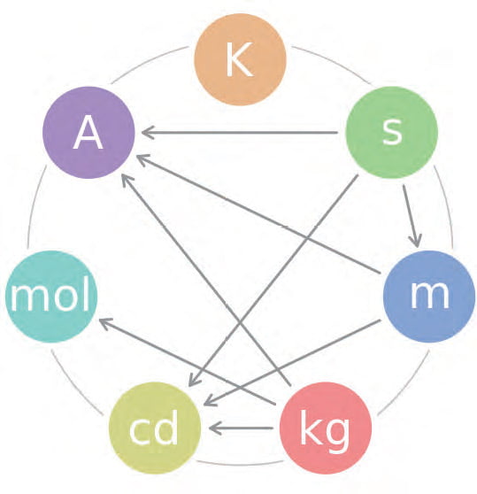
Figure 1: The seven base SI-Units and their interdependencies (clockwise from the top: Kelvin (temperature), second (time), meter (length), kilogram (mass), candela (luminous intensity), mole (amount of substance, and Ampere (electric current
SI-Units in CANopen device profiles
Only some the most common device profiles are covered by the review of this article. The presented concept also applies for other profiles. The purpose of the review is to briefly summarize the objects, where SI-Unit and scaling information is available. Readers are advised to read the device profile documents for further details. I/O devices according to CiA 401 can support units only if an optional objects are supported.
Unit for analog inputs is located at 6430h and for analog outputs at 6450h. However, because of the general purpose nature of I/O devices, there are significant risks for inconsistency. First, sensors and actuators cannot be unambiguously identified over analog signal path. Therefore it cannot be guaranteed that the connected sensor or actuator supports the signal type, for which the I/O device has been configured. Invalid combinations may look working properly over a wider signal value range, which may lead to incorrect behavior or even safety risk. Furthermore, the mentioned objects define the SIUnit, but no scaling, which may be implemented differently in different devices. Units are typically not used for outputs of joysticks and pedals. Joystick and pedal devices are indicated by higher word of the device type.
Transmitters according to CiA 404 are simple to manage. There are a set of objects defining the units and scalingof each channel.
SI-Unit with prefix is located at 6131h and the number of digits supported by the channel at 6132h. Scaling and offsets are used for calibration of the sensing element. Transmitters has been selected as a proof of concept because of the simple and unambiguous approach along with the common implementations. Transmitters can be mainly identified based on the higher word of device type – pressure and temperature transmitters support only analog inputs.
Encoders are even simpler, because CiA 406 clearly defines how to configure the encoder output signals. Furthermore, rotary and linear encoders have dedicated objects and the detailed encoder type is indicated in the higher word of the device type. Measuring step is given directly as µm for linear encoders. For rotary encoders, measuring step shall be computed from the number of steps per revolution. Measuring step for linear encoders is located at 6005h and the number of steps per revolution for rotary encoders is located at 6001h. The unit of speed information is always measuring units per second. Most common parameters, such as preset and CAM thresholds, use the same unit with scaled output signal. If scaling is disabled, default values of the scaling objects can be used instead. Scaling and preset are activated from operating parameters object, which is located at 6000h.
Hydraulic drives are covered by CiA 408. SI-Unit with prefix may be defined for each set-point and actual value signal. If unit is not defined, internal resolution shall be used as a relative set-point or actual value. Internal resolution is defined in the device profile and it may be either 16 bit (IR) or 32 bit (IR32). For example, set-point for spool position control is located at 6300h and pressure control at 6380h. Sub-index one of each object is used for the value itself.
SI-Units and prefixes are given in optional sub-indexes two and three. Same principle applies for actual spool position and actual pressure located at 6301h and 6381h respectively. Axis control set-points and actual values are included also as pairs, both with optional SI-Units and prefixes. Setpoints and actual values are located at 6500h and 6501h for velocity control, at 6580h and 6581h for force or pressure control and at 6600h and 6601h for position control.
Inclinometers follow device profile CiA 410. Main parameter for inclinometers is just a resolution of the output angles at 6000h.
The first potential source for errors is, that if 16- bit output signals are used, maximum resolution cannot be supported for the full 360 degrees measuring range. Main parameters, presets and differential offsets are using same unit with the output signals.
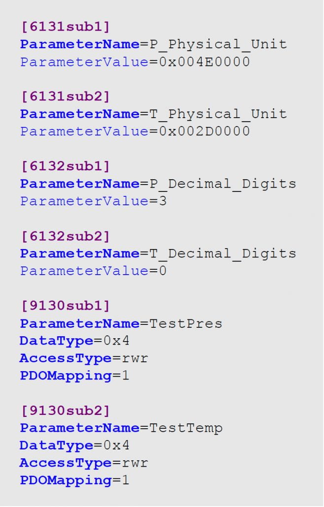
Figure 2: Excerpt of an example transmitter DCF with output signal and SI-Unit
CANopen project and DCF files
Each CANopen project consists of a set of DCF files – one for each device. The DCF files forming a project are listed in an additional project file, nodelist.cpj. System design tools may use their own file formats, but the main contents is always equal and it is easy to convert the proprietary files into standard format before other conversions. It is presented earlier, how calls to external add-on applications for e.g. code header export can be included into EDS and DCF files.
Main information source is included into object dictionary description part of DCF files. All defined meta information of objects may be utilized in application programming. Device commissioning section provides target location information, which may be used e.g. in diagnostics, and generating unique variable names. Information of device type and identity may be used for determining the type of target device and required format and contents of the export.
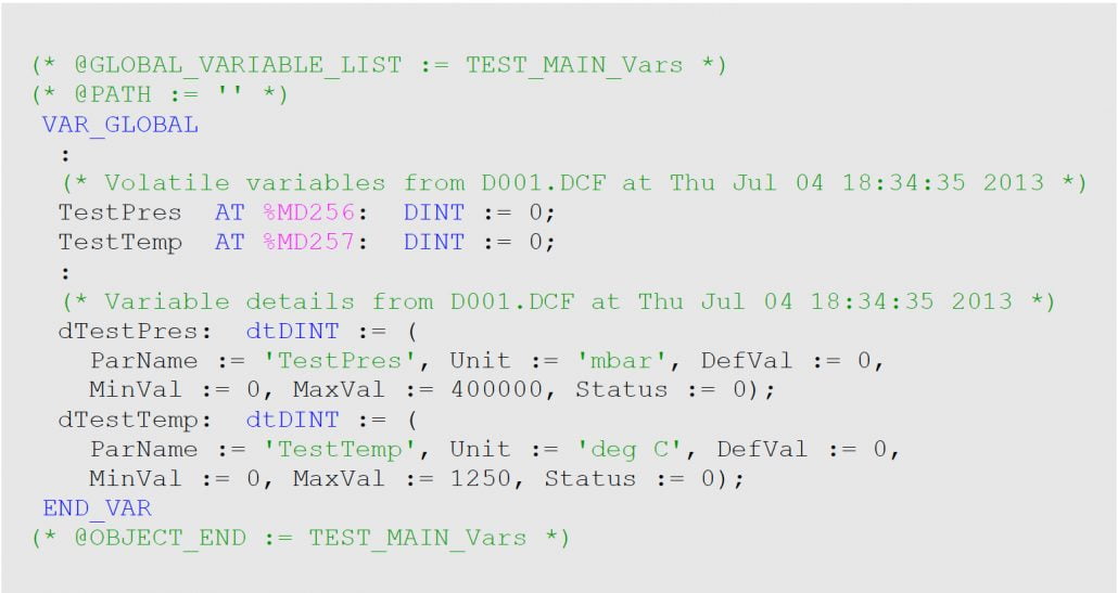
Figure 3: Excerpt of an example signal abstraction with SI-Units
Conversion process
Unit synchronization has been included as part of the IEC 61131- 3 communication abstraction generation presented earlier. There has been already a reservation for unit information in the presented code examples. The abstraction generation is divided into three parts – CANopen project parse, project analysis and device specific abstraction export. CANopen project parser just reads project information into memory as efficiently as possible. Parser independent of the analysis and export enables further improvement to e.g. support XDC files instead of DCFs when format becomes finalized and commonly adopted in the industry. Optionally nodelist.cpj may be replaced with proposed nodelist.graphml, if adopted as part of CiA 311 as proposed. Parameter values are defined during the system design, based on the system requirements. Thus, EDS files cannot be used as a source
Analysis part is source and target format independent, which enables flexible analysis of the project information and synthesis of information. Information synthesis is required, because a lot of information is distributed either in multiple objects of each DCF file or even in multiple DCF files. PDO connections between the devices can be followed based on CAN-IDs. Connections can be expanded into signal level by reading corresponding mapping information. After finding out signal connections, units need to be determined. As described earlier, supported device profile shall be read first. Then the supported units and scaling can read and computed from corresponding objects and added to the meta information of the signals. A simplified excerpt of a source DCF is presented in Figure 2.
The use of independent export enables device specific outputs. It is required because different formats are used by different IEC 61131- 3 development environments and because the exact contents of the export requires some target API specific declarations. In the future the variation will be reduced, because PLCopen has defined an XML-based standard information interchange format. The target may be automatically detected based on the values of device type and identity objects. An excerpt of target signal abstraction with full meta information is presented in Figure 3. Scaling is embedded as a part of the unit in the example, because a standardized approach does not exist.
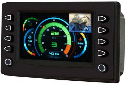
Figure 4: HMIs may convert the SI-Units to national units for convenience, but the CANopen devices must not communicate non SI-Units
Discussion and conclusion
Internal configuration affects on the units in most of the devices and therefore it is best to retrieve the units and scaling from the system project into abstraction layer of application software. Configuration is stored in standard DCF-files, where it can be accessed in a vendor, tool and device independent way. One interesting topic for future research is, how the device parameterization can be simplified.
The concept may be expanded to cover parameters and other device profiles, too. Main parameters of CANopen encoders, preset and CAMs are using the same SI-Unit and scaling with the position signal. CANopen transmitters use the same scaling for primary output signal, net output after tare function as well as optional controller and limit functions using input signals. Same defined scaling is used for all signals and parameters in CANopen inclinometers. Drive profiles are the most complex and will need to be analyzed further
All device profiles support objects using predefined format, from which type definitions may be defined in code header modules. In the future, along with the CiA 311, such information may be included into the XDD and XDC files. Such objects are e.g. polarity, filter enable, output error mode control and transmission event control objects for I/O devices. Transmitters support additionally sensor type, filtering and operational mode controls. Encoders support operational mode control and status in a fixed format. Both supported and pending warnings and alarms are clearly indicated in a predefined format. Hydraulic drives support fixed format objects for various device and program control purposes. Resolution and operating parameters are available in a predefined format for inclinometers.
SI-Unit and scaling information may also be added into system design tools to enable they to include such information into communication databases (DBC) to improve network analyses. Both DBC and many analyzer programs already support signal scaling and physical units. One approach could be standardization of the presentation of signal and parameter meta information – especially scaling – in IEC 61131-3 as co-operation of CiA and PLCopen.
Following the CANopen device profiles and standard storage formats is essential, also to get SIUnit and scaling management working. Traditional CANopen concepts provide good basis for unit management, without dependencies on system tools, device vendors or types. The approach may be easily improved further. The most essential is to get the XDD/ XDC formats finalized and into use because of more complete support of object units and enumeration.
Systematic and automated SI-Unit and scaling management will increase the design process performance further by reducing a need to read written manuals and enter such parameter values manually as a raw values. However, the most significant benefit is an avoidance of system configuration inconsistencies in projects, caused by the human mistakes.
Especially ever increasing functional safety requirements demand the realization of designed safety integrity level in system assembly and service. Systematic information management has a key role, because most of the design information inconsistencies potentially decrease the safety performance of systems.
There are fixed values for units and scaling in the simplest devices and it is wasting of memory to include corresponding constant information in read-only objects.
The information is mostly needed only in design time, one approach could be to introduce a totally new access type – info – for objects, for which the EDS files contain important constant value information for design tools but which are not implemented in the devices. Another approach could be to introduce a new object flag to indicate that an object is for information only and not implemented in the device. Modern systematic and automated design information management requires all possible meta information to be able to provide maximum efficiency.
